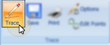
Main ribbon bar >  Trace. If the ceph already has a tracing, you are asked whether you want to remove all plotted points before continuing.
When you trace a ceph, SmartCeph guides you through all the structures and landmarks needed to fully digitize the ceph to comply with your preferred analysis type.
Main ribbon bar > Trace. If the ceph already has a tracing, you are asked whether you want to remove all plotted points before continuing.
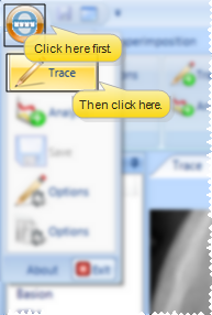
You can also initiate tracing from the  SmartCeph button.
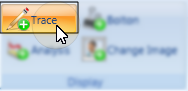
Notice the Trace button in your SmartCeph ribbon bar has a gold background while you are in tracing mode.
Reset option - When you click Trace for a ceph that has existing structures placed, you have the option of clearing all structures and starting over. If you do not reset the tracing, you can continue plotting points and adjusting structures as needed.
Calibration - (Non-dpi ceph only) If your ceph was not created using a digital pan ceph unit, SmartCeph prompts you for two points of measurement. Position your pointer on the metric ruler you have included on your ceph and click. Then move your pointer the distance you have set for measurement and click again. See "Set Up Trace Options" for details
Structure prompts & reference points - SmartCeph automatically places the first structure for you to position, with your cursor as close as possible to the appropriate landmark point. An illustration and description of the current structure appear in the Workspace window.
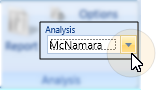
Confirm analysis type - Confirm the analysis you want to trace is selected in the Analysis section of the ribbon bar, to assure that you will be tracing all necessary structures. (If you have custom analysis templates that are not listed, be sure the Path to Custom Analysis field of your Analysis Options is correct.)
Abbreviation / audio prompt - You may or may not see landmark abbreviations and hear audio prompts during tracing. See "Set Up Trace Options" for details.
Zoom window option - You may or may not see the structure markings in the zoom window. See "Set Up Trace Options" for details.
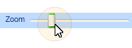
Enlarge / reduce image - Use the zoom slider to make the ceph bigger or smaller.
Display options - By default, the tracing shows on your ceph as you plot your structures, but you may enable other overlay as needed.
Trace - Enable / disable this tool in the Display section of the ribbon bar to add or remove the tracing from the display.
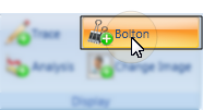
Bolton - Enable / disable this tool to add or remove the Bolton Standard from the display. See "Overlay Bolton Standard" for details about selecting and positioning a Bolton Standard.
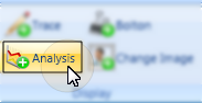
Analysis - Enable / disable this tool to add or remove the analysis from the display. If you attempt to display an analysis for which you have not placed all the necessary points, a message will inform you. See "View Analysis" for details.
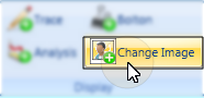
Change image - Click this tool to progress through the background image type: ceph , facial lateral photo, or none.
Position the structure - Use SmartCeph tools to position the structure as accurately as possible.
Move & rotate - Move your mouse to move the structure over the ceph. You can also right-click and drag to rotate the structure.
Confirm - Click your mouse button to "set" the structure at its current position.
Continue plotting - Once you "set" a structure in place, SmartCeph goes on to the next structure or landmark as listed in your Structures list. You can click a structure name at any time to place that structure instead. Once you have finished, SmartCeph will continue prompting you for the next structure in the list.
Multi-point structures - Some landmarks and structures will require multiple points or rotations. SmartCeph will prompt you for each position as necessary. For example, when you plot the incisors, you first click to plot the tip, then when you move your mouse, the structure rotates so you can plot the root.
Only required points placed - Only the points required for analysis are placed during the guided tracing. The additional points can be edited with the Edit Points feature. See "Edit Points" for details.
Calibrate with photo - If Upper Soft Tissue is included on your structure list, and the patient has a lateral facial photo, after all the points have been placed the patient’s lateral photo will appear and you will be prompted to identify Pronasale and Labial Sulcus. This enables SmartCeph to align the photo with the trace. If you import the lateral facial photo later, you can use the Calibrate tool to align the ceph with the photo. See "Recalibrate Images" for details.
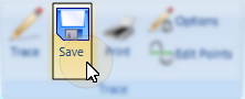
Save your work by selecting  Save on the ribbon bar, SmartCeph button, or Quick Access toolbar.
Save from ribbon bar:
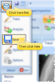
Save from SmartCeph button:
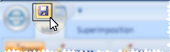
Save from Quick Access toolbar:
Save in Edge Imaging - Whenever you save a traced ceph in SmartCeph, a copy of the traced ceph, traced facial lateral photo, and trace wigglegram are automatically saved in the appropriate timepoint of the patient's Edge Imaging page. You can view these images from the Index layout, or from any layout that includes the Traced Lateral Ceph, Traced Photo, or Traced Lateral image types. Note that each time you save the trace, any existing SmartCeph images in that same timepoint will be overwritten.
Change the size of the ceph image with the zoom slider.
Check for accuracy in the zoom window.
Visually Enhance the ceph to see details more clearly. See "Visually Enhance Ceph" for details
Re-Plot - If you would like to re-plot a certain structure, simply click the name in the Structures List. The original positioning is removed and you are prompted for the landmark just as if you were tracing the ceph the first time.
Fine-tune - After you plot each structure, you may fine-tune the tracing by editing each point individually. See "Edit Points" for details.
 │
│  │
│  │
│ 
Ortho2.com │1107 Buckeye Avenue │ Ames, Iowa 50010 │ Sales: (800) 678-4644 │ Support: (800) 346-4504 │ Contact Us
Chat with Software Support │Chat with Network Engineering │ Chat with New Customer Care
Remote Support │Email Support │ Online Help Ver. 12/18/2015


